[mathjax]
At university we often think of series RLC circuits. L is a coil, R is a resistance, and C is a capacitor. The relationship between the voltage applied to each electronic component and the current is given as follows.
Voltage of Coil \(V_L\)
$$V_{L}(t)=L\frac{dI(t)}{dt}$$
Voltage of Resistance \(V_R\)
$$V_{R}(t)=RI(t)$$
Voltage of Capacitor \(V_C\)
$$V_{C}(t)=\frac{1}{C} \int I(t) dt=\frac{Q(t)}{C}$$
\(L\):Self
Characteristics of Coils
The coil hates the change of its internal magnetic field. Therefore, if a magnet approaches a coil from outside, a current in the coil flows in a direction to repel that magnet. This current is called an induced current.
Based on this, we’ll consider the behavior of the coil on the RL series circuit. We assume that a DC voltage is applied from the state where no current first flows. Then, since the coil does not like to change the internal condition, it tries to flow an induced current in the direction opposite to the applied voltage. The voltage generated by the coil to flow this induced current is called the counter electromotive force of the coil. However, there is a limit to this counter electromotive force, so if voltage is continuously applied, the current gradually flows in the applied direction. Eventually, the counter electromotive force becomes 0, and the current flowing by the circuit becomes constant.
What happens if you turn off the circuit in this state? Since the coil does not like to change the internal state, a counter electromotive force is generated in the direction in which the voltage had been applied. Then, as time goes on, its counter electromotive force also disappears, eventually becoming 0.
RL series circuit
Let’s consider this using mathematical expressions. The RL series circuit is shown in the figure as follows.
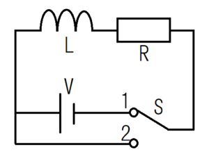
$$L\frac{dI(t)}{dt}+RI(t)=V・・・(1)$$
Behavior when switch 1 is turned on
Switch \(S\) to 1 when \(t=0\).
At the moment of entering Switch 1 (\(t=0\)), the current does not flow in the circuit due to the counter electromotive force of the coil (\(I(0)=0\)). Solving the differential equation (1) based on this initial condition yields the following equation.
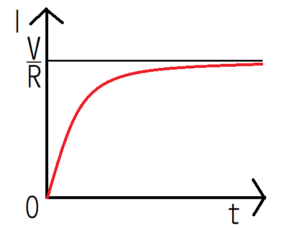
$$I(t)=\frac{V}{R}(1-e^{-\frac{R}{L}t})$$
When the time passes sufficiently (\(t \to ∞\)), the current becomes \(I=\frac{V}{R}\) because \(e^{-\frac{R}{L}t} \to 0 \). According to Ohm’s law, this current value coincides with that in the case where only resistance \(R\) exists in the series circuit. Therefore, it can be seen that the counter electromotive force of the coil becomes 0 with \(t \to ∞\). Graphing the current \(I(t)\) in the circuit, it looks like the following.
Behavior when switch 2 is turned on
Next, we’ll investigate the change of the current \(I(t)\) when switching to switch 2 at \(t=0\) after sufficient time has passed in switch 1.
Unlike the above equation (1), there is no electric power sources on the circuit, so \(V=0\).
$$L\frac{dI(t)}{dt}+RI(t)=0$$
solving this using the initial condition (\ (t=0⇒I(0)=\frac{V}{R}\))), we get
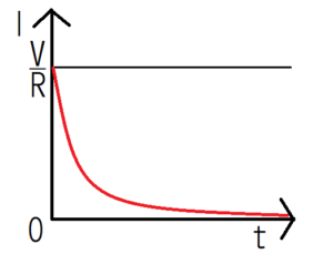
$$I(t)=\frac{V}{R}e^{-\frac{R}{L}t}.$$
From this equation, it is understood that the current flows immediately after switching to the switch 2, but it decreases as time elapses. Finally, Graphing the current \(I(t)\) in the circuit.
Characteristics of Resistances
According to the Ohm’s law, \(V_{R}=RI\).
By the way, the relational expression \({\bf j}=σ{\bf E}\) of electric current density \({\bf j}\), electric conductivity \(σ\), electric field \({\bf E}\) is called Ohm’s law too.
Characteristics of Capacitors
A capacitor has the property of storing electric charge. As an indicator of how much charge can be stored, there is an index called electrostatic capacity \(C\).
Just by facing the conductive plates, the condenser with the simplest structure is completed. From the equation below, it can be seen that the capacitance \ (C \) increases as a result of sandwiching a dielectric(insulator) between the conductive plates.
$$C=ε\frac{S}{d}=ε_{0}ε_{r}\frac{S}{d}$$
\(S\):Area of conductor plates \(d \):Distance between conductor plates \(ε \): Dielectric constant of the insulator \(ε_{0}\): Dielectric constant of vacuum \(ε_{r}\):Relative permittivity
When a current is passed through a capacitor having no charge, the capacitor starts to store electric charge. In the absence of charge, we can consider the resistance of the capacitor is zero. However, as the charges gradually accumulate in the capacitor, no current flows in the circuit. Eventually, when the charge accumulates to the maximum and charging is finished, current no longer flow.
RC series circuit
Let’s consider this using mathematical expressions. The RL series circuit is shown in the figure as follows.
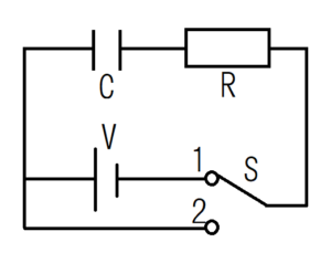
$$\frac{1}{C} \int I(t) dt+RI(t)=V・・・(2)$$
Behavior when switch 1 is turned on
The charge contained in the capacitor is represented by \(q (t)\). Then, Rewrite the equation (1) with the equation \(\frac{1}{C} \int I (t) dt=q(t)\) between the current \(I (t)\) and the charge \(q(t)\).
$$q(t)+RC\frac{dq(t)}{dt}=VC$$
Assuming the capacitor has no charge at \(t= 0\), the initial condition is \(q(0)=0\). Then solve the differential equation with the initial condition and we get the following one.
$$q(t)=VC(1-e^{-\frac{1}{RC}t})$$
By differentiating both sides of the above equation with respect to \(t\), we can convert the above equation into the equation for current \(I(t)\).
$$I(t)=\frac{V}{R}e^{-\frac{1}{RC}t}$$
From this equation, we can say the current at \ (t = 0 \) is \ (I (t) = \ frac {V} {R} \) and the resistance of the capacitor itself is zero. However, when sufficient time has elapsed and the charging of the capacitor is finished, no current flows in the circuit.
The shape of the graph is the same as that of the RL circuit with switch 2.
Behavior when switch 2 is turned on
Next, we’ll investigate the change of the current \(I(t)\) when switching to switch 2 at \(t=0\) after sufficient time has passed in switch 1.
$$\frac{1}{C} I(t)+R\frac{dI(t)}{dt}=0$$
Solve this differential equation using the initial condition \(I(0)=-\frac{V}{R}\) and you can obtain the following expression.
The reason why the sign of the initial condition is negative will be described later.
$$I(t)=-\frac{V}{R}e^{-\frac{1}{RC}t}・・・(3)$$
The above function of the current \(I\) of switch 2 is similar to that of switch 1. From this equation (3), it is found that when the switch 2 is turned on, the electric charge charged in the capacitor is discharged and the current becomes 0 when all the charge is released.
Why the Initial Condition is minus?
Be aware that the positive and negative signs are reversed from those when switch 1 is turned on. The reason for reversing the sign is that changing the switch changes the direction of flow of electrons and holes.
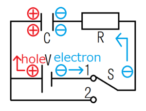
When connected to switch 1, electrons move counterclockwise and accumulate on the plate on the right side of the capacitor. On the other hand, the holes move clockwise in the circuit and accumulate in the plate on the left side of the capacitor.
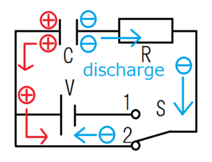
After that, when connected to switch 2, electrons are emitted from the plate on the right side of the capacitor and move the circuit clockwise. On the other hand, holes are emitted from the plate on the left side of the capacitor and move counterclockwise. Compared with the figure of switch 1, since the direction of electrons and holes are opposite, the direction of current is also reversed. Therefore, minus must be added to the initial condition.
Conclusion
・A coil generates a voltage in the direction opposite to the voltage applied to the coil.
・While a capacitor is charging, it looks like conducting electricity. Then when a capacitor has finished charging, it come not to conduct electricity.